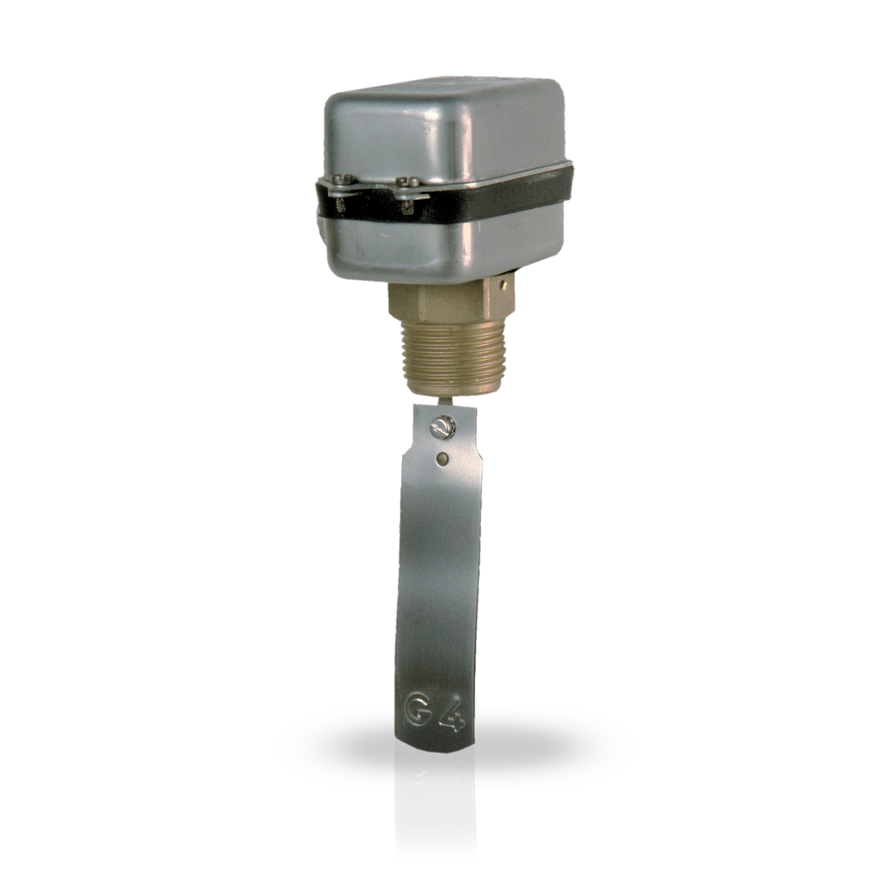
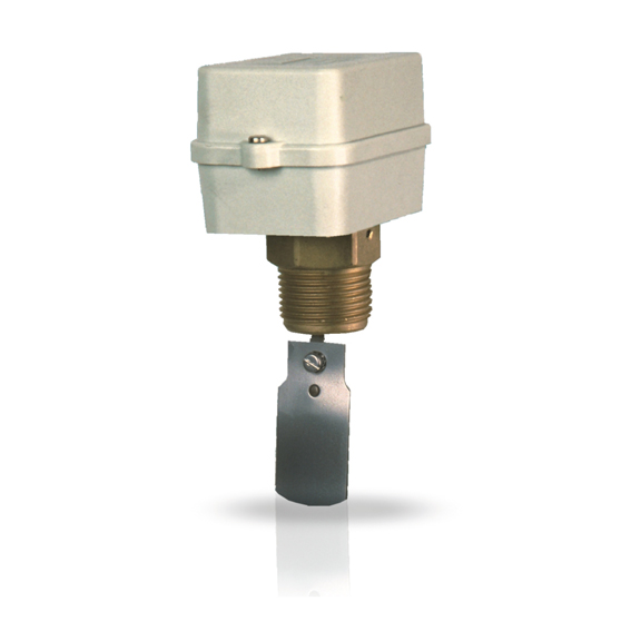
Liquid flow switches with stainless steel casing and paddle
-
DESCRIPTION
General features0
Flow switches are used to signal, control and regulate the flow in a pipe; for the control of pumps, burners, compressors,
alarm signals, motorized valves.- Type FF81:
- Casing in shock- proof thermoplastic with self- retaining screws
- Threaded brass connection G1 Nylon cable gland G 3/ 8
- AISI 301 stainless steel blades from G1 to G4
- Protection class 2
- Type FF84:
- Casing in stainless steel with self- retaining screws
- Threaded brass connection G1
- Nickel- plated brass cable gland G 3/ 8
- Protection class 1
- AISI 301 stainless steel blades from G1 to G10
- Electric connections on Faston 6.3 ( provided)
- SPDT single- pole switching microswitch
Electric features- Rated insulation voltage Ui 380V~
- Continuous duty rated current Ith 10A
-
ADVANTAGES
0
Flow switches are used to signal, control and regulate the flow in a pipe; for the control of pumps, burners, compressors,
alarm signals, motorized valves.Advantages -
TECHNICAL SPECIFICATION
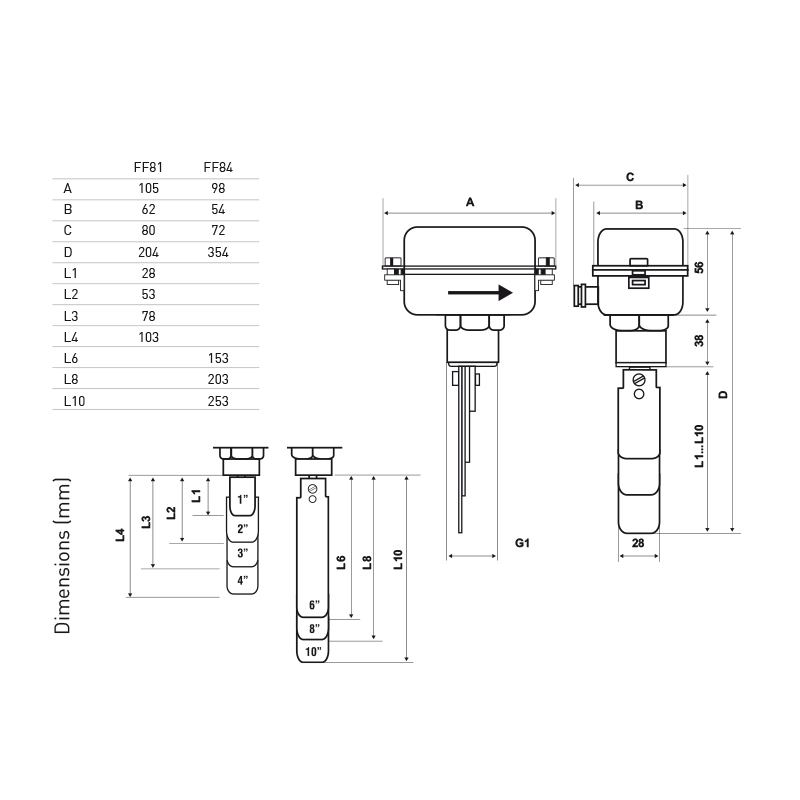
CODE PIPE DIAMETER MINIMUM CALIBRATION VALUE (dm³/sec) WITH FLOW INCREASING MINIMUM CALIBRATION VALUE (dm³/sec) WITH FLOW DECREASING MAXIMUM CALIBRATION VALUE (dm³/sec) WITH FLOW INCREASING MAXIMUM CALIBRATION VALUE (dm³/sec) WITH FLOW DECREASING MALE CONNECTION MAXIMUM OPERATING PRESSURE PROTECTION DEGREE UNIT WEIGHT KG FF81 G 1 0.26 0.16 0.58 0.53 G1” 10 bar IP54 0.39 G 2 0.8 0.6 1.6 1.7 G1” 10 bar IP54 0.39 G 3 1.7 1.2 3.2 3 G1” 10 bar IP54 0.39 G 4 2.2 1.7 5.1 4.8 G1” 10 bar IP54 0.39 FF84 G 1 0.26 0.16 0.58 0.53 G1” 10 bar IP54 0.67 G 2 0.8 0.6 1.6 1.7 G1” 10 bar IP54 0.67 G 3 1.7 1.2 3.2 3 G1” 10 bar IP54 0.67 G 4 2.2 1.7 5.1 4.8 G1” 10 bar IP54 0.67 G 6 4.7 3.4 9 8.5 G1” 10 bar IP54 0.67 G 8 12.9 10.7 26 25.2 G1” 10 bar IP54 0.67 G 10 26.5 22 43.5 41 G1” 10 bar IP54 0.67 -
HOMOLOGATION AND INSTALLATION
Homologation
- Complies with CEI EN 60947-5-1 standards
Installation and use - TECHNICAL LITERATURE
-
FAQS


